|


2003
Maine Wastewater Salary Survey as conducted by the Maine Wastewater Control
Association
2003 Maine
Wastewater Rate Survey conducted by the Maine Rural
Water Association

Maine DEP Monthly
O & M Newsletter
Maine and WEF's
Operation Forum
Penobscot Watershed and Development of a TMDL
EPA Binational Toxics
Strategy
Maine Rural Water
Association
Maine Wastewater
Operator Certification
Guide
Maine Is Technology
Newsletter
Maine
Wastewater Control Association

Maine
Wastewater Engineering
Firms
| |
AERATED
LAGOON TECHNOLOGY

by
Linvil G. Rich
Alumni Professor Emeritus
Department of Environmental
Engineering and Science
Clemson University -
Clemson, SC 29634-0919 USA
Email: lrich@clemson.edu;
Tel. (864) 656-5575; Fax (864) 656-0672
Technical Note Number 7
MIXED-LIQUOR RECYCLE (MLR)
LAGOON NITRIFICATION SYSTEM
As
was discussed in Technical Note 6, during warm summer months, some
nitrification generally occurs in most aerated lagoons. However, such
nitrification is usually unpredictable and cannot be depended upon to meet
effluent limits, especially during the winter months. Therefore, for aerated
lagoons to be considered as viable processes for nitrification, the lagoon
process must be modified so that the solids age is uncoupled from the hydraulic
retention time (HTR). This can be accomplished either through sedimentation in
clarifiers with solids recycle or through the retention of the solids in the
aeration basin by use of sequencing batch reactor (SBR) technology. The latter
approach has been used in single basin, continuous-feed, intermittent discharge
(CFID) treatment systems for many years both in Australia and the United States.
Their performance has been well documented (Goronszy 1979, Arora et al.,
1985, Deeney et al. 1991). Although generally successful, some of the
CFID systems have had major operational problems as the result of
short-circuiting and/or sludge bulking. However, such problems can be minimized,
or even eliminated, by modifying the design to deal directly with conditions
that promote the problems. The mixed-liquor recycle (MLR) lagoon system
incorporates such modifications. The MLR nitrification system, which is not
proprietary, is illustrated in Fig. 1. The system consists of two earthen basins
in series – a reactor basin for ammonia and CBOD5 removal and a
sludge basin for solids stabilization and storage. The overall configuration and
size of such a system are discussed in the following paragraphs. Design details
are to be found in Rich (1999).
REACTOR BASIN
The reactor basin is divided into two cells by
a floating curtain wall or a hard wall. The first cell is aerated continuously,
whereas the second cell is aerated intermittently in a controlled cycle that
includes sedimentation and supernatant decant. Mixed liquor is recycled from the
second cell to a manhole just upstream from the headworks of the plant. There it
is mixed with the incoming sewage. The mixture flows through the headworks and
into the first cell in a continuous stream. The two cell configuration
eliminates short circuiting through the reactor basin as well as modulates the
peaks of the diurnal loading pattern. Furthermore, by designing for
nitrification to occur in the second cell, the system separates the oxygen
demand of nitrifiers from that of the heterotrophs creating more favorable
conditions for nitrifiers. The mixed liquor recycle promotes the contact of the
biomass with the soluble CBOD5 in the sewage, thus reducing the
tendency for filamentous bulking.
The nitrification process is controlled
through the continuous wasting of the mixed liquor from the reactor basin to the
sludge basin. Such control can be accomplished by diverting a portion of the
recycle flow. The flow rate of the diverted mixed liquor will determine the
solids retention time at which the process is operated. The rate can be
controlled simply by adjusting a hand valve inserted in the piping for the
diverted flow.
In addition to aeration equipment and mixers
to ensure solids suspension, equipment required includes a programmable logic
controller (PLC), liquid level sensors, a low-head recycle pump, and a decant
device. The latter can be as sophisticated as a decanter designed for sequencing
batch reactor technology, or as simple as pumps or fixed pipes with automatic
valves.
The design retention time in the reactor basin
should be such that sufficient volume is provided to dilute peak organic and
ammonia loads, yet low enough to reduce the power requirements for solids
suspension. Therefore, it is recommended that the retention time at design flow
rate, HRTD, be a function of the ratio of the initial flow rate, QI,
and the design flow rate, QD. If QI/QD >
0.5, then HRTD should be 2d. If QI/QD < 0.5,
then HRTD should be 1d.
SLUDGE BASIN
The sludge basin is designed for solids
stabilization by benthal processes and multiyear sludge storage. Furthermore,
the basin serves as an effluent balance tank to attenuate the intermittent
decants from the reactor basin. Two floating curtain walls are used to divide
the basin into three cells, each with a hydraulic retention time of about one
day at the design flow rate. All cells are aerated, but not at a rate that
interferes with sedimentation. Aeration is required in the sludge basin to
prevent ammonia feed back from the bottom solids, and to eliminate dead spaces
in the water column where algae can become established and grow. If QI/QD
> 0.5, then the HRTD should be 3d. If QI/QD
< 0.5, then the HRTD should be 2d.
EXISTING SYSTEMS
Although the MLR nitrification system must still
be considered innovative, two such systems are currently in operation and a
third is under design. The two systems in operation are located close to
Liberty, SC. The Cramer lagoon initially was a dual-power, multicellular aerated
lagoon system consisting of a separate reactor basin followed by a sludge basin
divided into three cells in series. The upgrade consisted of dividing the
reactor basin into two cells in series with a hard wall, fitting both cells with
aerators and mixers, providing a decant pump and line to the sludge basin, and a
mixed liquor recycle pump and a line to a manhole above the headworks of the
plant. A programmable logic controller (PLC) was installed to control aerators,
mixers, and pumps. At the present, discharge from the second cell of the reactor
is on a six-hour cycle. The Cramer system is permitted at 157,000 gal/d. Cost of
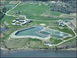
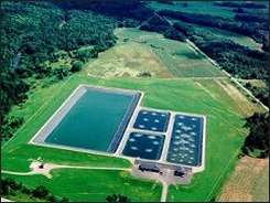
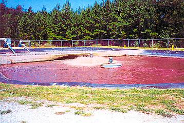
the upgrade was $312,000. Photographs of the Cramer lagoon system are shown in
Fig. 2.
Initially, the Roper lagoon was a single-basin,
facultative aerated lagoon. The upgrade consisted of dividing the existing basin
into two cells in series with a floating curtain wall, fitting both cells with
aerators and mixers, a decant pump and line to a new sludge basin, and a recycle
pump and line to a manhole above an enlarged headworks. The upgrade included
also a new three-cell sludge basin, with aerators, and an enlarged
chlorination-dechlorination facility. A PLC was installed for control of the
aerators, mixers and pumps. The Roper system is permitted at 500,000 gal/d. Cost
of the upgrade was $1,100,000.
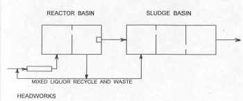
Figure 1.
Mixed-liquor recycle (MLR)
nitrification system
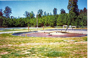
Reactor basin with first cell in foreground
Closer view with decant and mixed-liquor recycle
pumps in left background
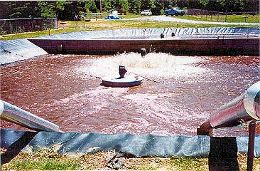
Second cell of reactor basin in foreground with headworks in
far background
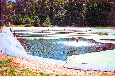
Three-cell sludge basin with chlorination facilities in far
background
Figure 2.
Photographs of the Cramer mixed-liquor nitrification system at Liberty, SC.
REFERENCES
Arora, M. L. et al.
(1985). “Technology evaluation of sequencing batch reactors.” J. WPCF,
57(8),867-875.
Deeney, K. et al.
(1991). “Implementation of sequencing batch reactor technologies in the United
States.” 64th Annual Conf., WPCF, Toronto, Canada.
Goronszy, M. C. (1979).
“Intermittent operation of the extended aeration process for small systems.”
J. WPCF., 51(2),274-287.
Rich, L. G. (1999).
High-Performance Aerated Lagoon Systems. American Academy of Environmental
Engineers.Annapolis, MD.

|