 |
|
 |
| Mission | Search | Acknowledgements | Discussion Group | Contact Us | Links | ||
| ||||||
|
Maine DEP Monthly
Maine and WEF's
Penobscot Watershed and Development of a TMDL
Maine Rural Water
Maine
Wastewater Control Association |
Waldoboro Utility
District
| ||||||||||||||||||||||||||||||||||||||||||||||||||||||||||||||||||||||||||||||||||||
|
Project Funding Sources |
|
| DEP Grant |
$3,200,000 |
| Rural Development Grant |
$1,000,000 |
| Rural Development Loan |
$1,000,000 |
|
Total |
$5,200,000 |
There were no tax monies involved in
the financing and all costs will be paid back by the users of the sewer system.
|
Time Table |
|
| Spring 1997 | Prepare preliminary Design |
| Spring 1997 | Determine Location of New Facilities |
| Spring 1997 | Take project to voters for approval. |
| Summer 1997 | Prepare Final Design |
| Fall 1997 | Approvals and permits from regulatory agencies |
| Winter 1997 / 98 | Put Project out to bid |
| Spring 1998 | Begin Construction |
| Fall 1999 | Finish Construction and start up new plant |
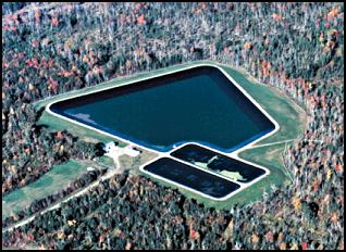
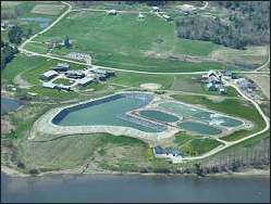
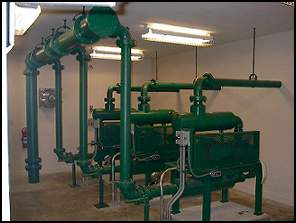
New Treatment Plant Design
A sewer collector system covers most of the village area transports the wastewater to the Main Pump Station just off Main Street near the river. This station provides screening prior to pumping it to the Railroad Pump Station located between Route 220 and Route One next to the railroad. From here the wastewater is pumped thru a force main to the treatment facility. The Waldoboro Wastewater Treatment Facility provides secondary treatment thru aerated facultative lagoons. Treated effluent may be spray irrigated from April 15th to November 15th and is stored during the remaining periods of the year (November 16th to April 14th.
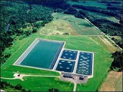
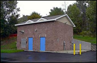
The treatment facility consists of two aerated lagoons, a storage lagoon, inlet and outlet structures, mechanical building and spray fields.
Process Description
The wastewater received at the treatment facility is pumped from the Railroad and Main Pump Stations after passing through the mechanical bar screen and into the wet wells. The volume is measured as it is and then pumped to the lagoons for aeration, biological oxidation and sedimentation. The wastewater enters Lagoon No. 1 through a diffuser pipe that distributes the flow across the lagoon.
Lagoon aeration is through a diffused air system that is tapered to match the oxygen demand. Most of the aeration capacity is provided in Lagoon No. 1 with most of the aeration at the inlet end because of the high organic loads of the wastewater.
 Aeration tapering is accomplished
through the use of larger aeration tubes at the inlet end of Lagoon No. 1 and by
changing the spacing between the air laterals and aerators. The aerators are
close together at the inlet end of the Lagoon No. 2.
Aeration tapering is accomplished
through the use of larger aeration tubes at the inlet end of Lagoon No. 1 and by
changing the spacing between the air laterals and aerators. The aerators are
close together at the inlet end of the Lagoon No. 2.
Following treatment, the wastewater passes from Lagoon No. 2 to the storage lagoon where it can be land applied in season or it can be stored. During the period of land application the treated wastewater is pumped from the storage lagoon and spray irrigated with a line shaft centrifugal pump and fixed sprinkler system. During non-discharge periods the effluent is stored in the storage lagoon.
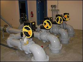 An effluent magnetic flow meter,
with readout and totalizer are located inside the mechanical building. The flow
meter measures the discharge to the spray fields. The spray irrigation rate is
recorded to maintain discharge records. The discharge rate will vary depending
on which field is being used. The pumping rate should be determined for each
field anytime conditions change. Under normal conditions one filed is sprayed at
a time.
An effluent magnetic flow meter,
with readout and totalizer are located inside the mechanical building. The flow
meter measures the discharge to the spray fields. The spray irrigation rate is
recorded to maintain discharge records. The discharge rate will vary depending
on which field is being used. The pumping rate should be determined for each
field anytime conditions change. Under normal conditions one filed is sprayed at
a time.
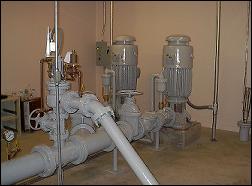
|
Irrigation System Pumps |
 |
Lagoon Specifications
![]()
| Lagoons | No.1 | No. 2 | No. 3 (storage) |
| Volume | 2.77 MG | 2.71 MG | 47 MG |
| Lagoon Sizes | 400' x 138 x 12 to15'd | 400' x 138 x 12 to 15'd | 650'' x 600' x 4 to 20'd |
| Lagoon Acreage | 1.26 acres | 1.26 acres | 9.0 acres |
| Aeration | Fine Bubble | Fine Bubble | Fine Bubble |
| Number of Units | 16 | 10 | 0 |
|
|
System Information
![]()
| Design Flow | 0.150 MGD |
| Actual Flow | 0.110 MGD |
| Discharge To | Land Application |
| Year Built | 2001 |
| Design Engineers | Dirigo |
| Septage Received | No |
| Collector System | 5 ¼ miles of gravity sewer, 117 manholes, 3 miles of force main and 5 pump stations |
| Staff Size | 3 part time |
| Number of Users | 410 |
| Billing Software | Northern Data Systems |
| Comments | 150 Spray heads will cover approximately 75 acres. Spray pump is planned to b a 100 hp vertical turbine pump with capacity to pump 1500 gpm. |
|